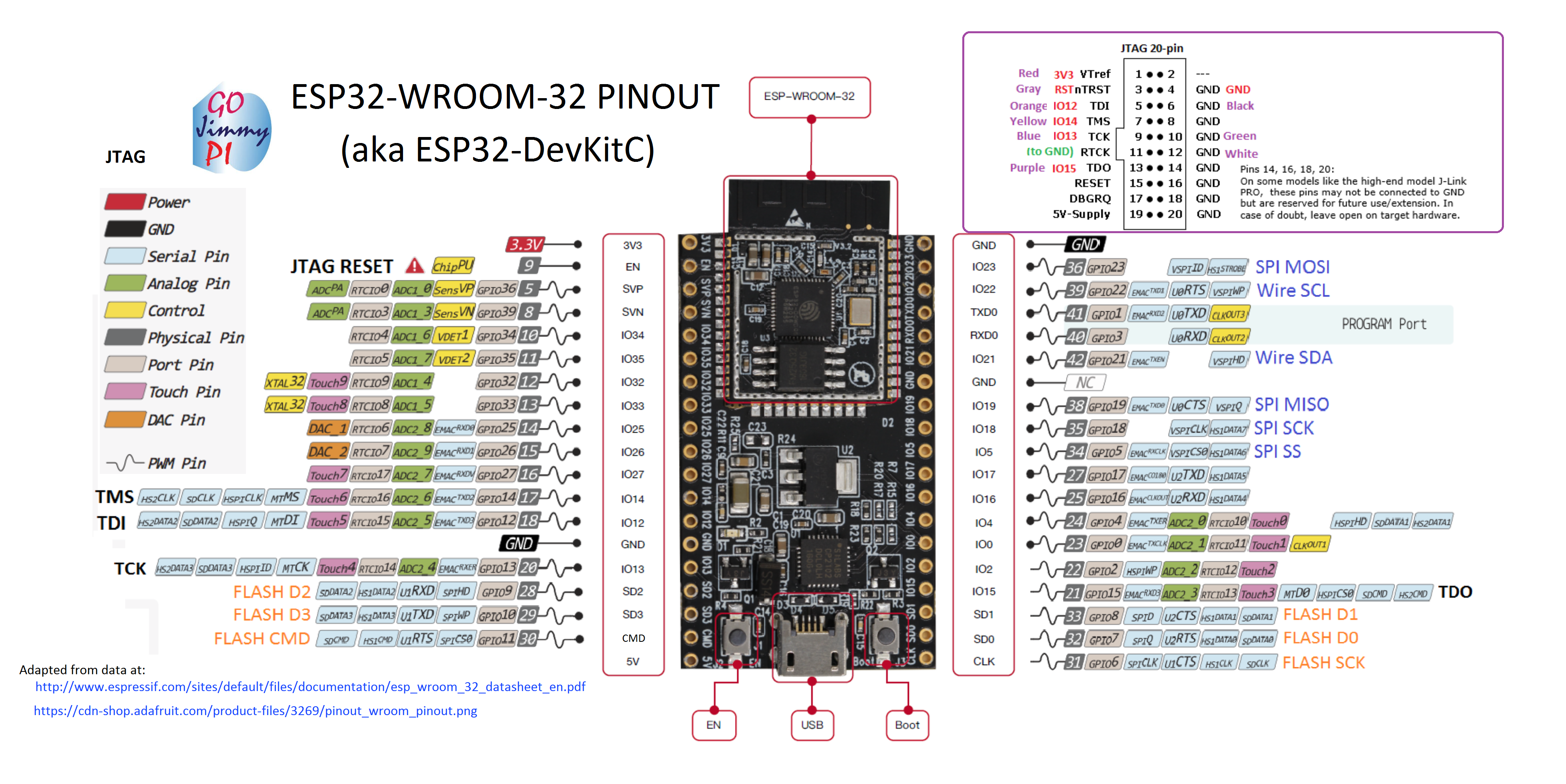
===== Espressif ESP32 =====
[[https://espressif.com/en/products/hardware/esp32/resources|Dokumentation and Datasheet]]\\
[[https://leanpub.com/kolban-ESP32|Kolban's Book on ESP32]]\\
[[https://github.com/pcbreflux/espressif]]\\
{{:esp32:esp323_pinout_wroom_pinout.png?600|}}\\
----
===== Serial to USB Driver =====
- [[https://www.silabs.com/products/development-tools/software/usb-to-uart-bridge-vcp-drivers| SiLabs CP2104]]\\
- [[https://github.com/himalayanelixir/Arduino_USB_Drivers|CH340]]\\
----
==== Espressif ESP32 Development Board ====
The HW-607 ESP32 Board with a CH340G Serial to USB chip.\\
[[https://www.adafruit.com/product/3269|ESP32 Development Board]]\\
[[https://dl.espressif.com/doc/esp-idf/latest/get-started/get-started-devkitc.html]]\\
 === Upload a Sketch ===
The Examples for the ESP32 become visible after selecting **ESP32 DEV MODULE** in the Arduino IDE.\\
Set the flashing speed to 460800 or lower (115200).\\
Upload your sketch.\\
It could be necessary to start the IDE with administrator rights, too.\\
----
=== Special Hardware Configuration ====
** The I/O pins are not 5V-tolerant! **\\
Use 3.3V instead.\\
\\
The build in LED is on GPIO 2.\\
\\
GPIO 34, 35, 36, 37, 38 and 39 are input only. And don't have a software pull-up or pull-down functions. One has to use an external 10k pull-up resistor.\\
\\
GPIO 6, 7, 8, 9, 10 and 11 are used for the SPI flash chip and can't be used for any other purposes.\\
----
==== WeMos ESP32 OLED Board ====
{{:esp32:ita4kni.jpg?600|}}\\
The OLED is connected like that:\\
pin5 - SDA
pin4 - SCL
The I2C address of the screen is 0x3c.\\
#include "SSD1306.h"
SSD1306 display(0x3c, 5, 4);
Librarie:\\
[[https://github.com/squix78/esp8266-oled-ssd1306]]\\
Board: ESP32 Dev Module
Manuals:\\
[[http://www.instructables.com/id/ESP32-With-Integrated-OLED-WEMOSLolin-Getting-Star/]]\\
[[https://techtutorialsx.com/2017/12/02/esp32-arduino-interacting-with-a-ssd1306-oled-display/]]\\
----
==== Arduino core for ESP32 WiFi chip ====
[[https://github.com/espressif/arduino-esp32]]\\
Workaround for Arch Linux:\\
Install the latest Arduino IDE
sudo pacman -S arduino
Install Git
sudo pacman -S git
Download and run get-pip.py
wget https://bootstrap.pypa.io/get-pip.py
sudo python get-pip.py
Install PySerial
sudo pip install pyserial
Make a folder in the Arduino folder
sudo mkdir -p /usr/share/arduino/hardware/espressif
cd /usr/share/arduino/hardware/espressif
Download ESP32 and run get.py
sudo git clone https://github.com/espressif/arduino-esp32.git esp32
cd esp32
sudo git submodule update --init --recursive
cd tools
sudo python2 get.py
----
==== Programming the ESP32 ====
IO pin 34 and pin 35 don't work!\\
**ESP-IDF Programming Guide**\\
[[https://esp-idf.readthedocs.io/en/v2.0/index.html]]\\
**the 8bit DAC:**\\
[[https://esp-idf.readthedocs.io/en/v2.0/api/peripherals/dac.html]]\\
#include
void setup() {
}
void loop() {
for (int i=0; i<255; i++){
dac_out_voltage(DAC_CHANNEL_1, i);
}
}
Output is a signal between 0 and 3.2V with 76Hz.
----
==== Adafruit HUZZAH32 – ESP32 Feather Board ====
[[https://www.adafruit.com/product/3405|Adafruit HUZZAH32 – ESP32 Feather Board]]\\
[[https://learn.adafruit.com/adafruit-huzzah32-esp32-feather|Adafruit Learn Guid]]\\
----
===== DAC and ADC =====
**ADC**\\
analogRead(GPIO);
analogReadResolution(resolution) //set the sample bits and resolution in bits, 9 => (0 – 511) and 12 => (0 – 4095), default 12
analogSetWidth(width) //set the sample bits and resolution
analogSetCycles(cycles) //set the number of cycles per sample, range: 1 - 255, default 8
analogSetSamples(samples) //set the number of samples in the range, default is 1 sample
analogSetClockDiv(attenuation) //set the divider for the ADC clock, range: 1 - 255, default is 1
analogSetAttenuation(attenuation) //sets the input attenuation for all ADC pins. Default is ADC_11db. Accepted values:
ADC_0db: sets no attenuation (1V input = ADC reading of 1088).
ADC_2_5db: sets an attenuation of 1.34 (1V input = ADC reading of 2086).
ADC_6db: sets an attenuation of 1.5 (1V input = ADC reading of 2975).
ADC_11db: sets an attenuation of 3.6 (1V input = ADC reading of 3959).
analogSetPinAttenuation(pin, attenuation) //sets the input attenuation for the pin, default is ADC_11db
adcAttachPin(pin) //attach a pin to ADC, returns TRUE or FALSE
adcStart(pin) //starts an ADC conversion on attached pin’s bus
adcBusy(pin) //check if conversion on the pin’s ADC bus is running, returns TRUE or FALSE
adcEnd(pin) //get the result of the conversion: returns 16-bit integer
taken from: [[https://www.malabdali.com/esp32-adc-and-dac/]]
----
**DAC**\\
The ESP32 has two DAC pins, GPIO25 and GPIO26. The resolution is 8 bits.\\
dacWrite(25, Value); // 255=3.3V 128=1.65V 0=0.0V
For generating a sine wave one finds a good manual here: [[https://www.xtronical.com/basics/audio/dacs-on-esp32/|DAC’s on ESP32]]\\
----
=== Upload a Sketch ===
The Examples for the ESP32 become visible after selecting **ESP32 DEV MODULE** in the Arduino IDE.\\
Set the flashing speed to 460800 or lower (115200).\\
Upload your sketch.\\
It could be necessary to start the IDE with administrator rights, too.\\
----
=== Special Hardware Configuration ====
** The I/O pins are not 5V-tolerant! **\\
Use 3.3V instead.\\
\\
The build in LED is on GPIO 2.\\
\\
GPIO 34, 35, 36, 37, 38 and 39 are input only. And don't have a software pull-up or pull-down functions. One has to use an external 10k pull-up resistor.\\
\\
GPIO 6, 7, 8, 9, 10 and 11 are used for the SPI flash chip and can't be used for any other purposes.\\
----
==== WeMos ESP32 OLED Board ====
{{:esp32:ita4kni.jpg?600|}}\\
The OLED is connected like that:\\
pin5 - SDA
pin4 - SCL
The I2C address of the screen is 0x3c.\\
#include "SSD1306.h"
SSD1306 display(0x3c, 5, 4);
Librarie:\\
[[https://github.com/squix78/esp8266-oled-ssd1306]]\\
Board: ESP32 Dev Module
Manuals:\\
[[http://www.instructables.com/id/ESP32-With-Integrated-OLED-WEMOSLolin-Getting-Star/]]\\
[[https://techtutorialsx.com/2017/12/02/esp32-arduino-interacting-with-a-ssd1306-oled-display/]]\\
----
==== Arduino core for ESP32 WiFi chip ====
[[https://github.com/espressif/arduino-esp32]]\\
Workaround for Arch Linux:\\
Install the latest Arduino IDE
sudo pacman -S arduino
Install Git
sudo pacman -S git
Download and run get-pip.py
wget https://bootstrap.pypa.io/get-pip.py
sudo python get-pip.py
Install PySerial
sudo pip install pyserial
Make a folder in the Arduino folder
sudo mkdir -p /usr/share/arduino/hardware/espressif
cd /usr/share/arduino/hardware/espressif
Download ESP32 and run get.py
sudo git clone https://github.com/espressif/arduino-esp32.git esp32
cd esp32
sudo git submodule update --init --recursive
cd tools
sudo python2 get.py
----
==== Programming the ESP32 ====
IO pin 34 and pin 35 don't work!\\
**ESP-IDF Programming Guide**\\
[[https://esp-idf.readthedocs.io/en/v2.0/index.html]]\\
**the 8bit DAC:**\\
[[https://esp-idf.readthedocs.io/en/v2.0/api/peripherals/dac.html]]\\
#include
void setup() {
}
void loop() {
for (int i=0; i<255; i++){
dac_out_voltage(DAC_CHANNEL_1, i);
}
}
Output is a signal between 0 and 3.2V with 76Hz.
----
==== Adafruit HUZZAH32 – ESP32 Feather Board ====
[[https://www.adafruit.com/product/3405|Adafruit HUZZAH32 – ESP32 Feather Board]]\\
[[https://learn.adafruit.com/adafruit-huzzah32-esp32-feather|Adafruit Learn Guid]]\\
----
===== DAC and ADC =====
**ADC**\\
analogRead(GPIO);
analogReadResolution(resolution) //set the sample bits and resolution in bits, 9 => (0 – 511) and 12 => (0 – 4095), default 12
analogSetWidth(width) //set the sample bits and resolution
analogSetCycles(cycles) //set the number of cycles per sample, range: 1 - 255, default 8
analogSetSamples(samples) //set the number of samples in the range, default is 1 sample
analogSetClockDiv(attenuation) //set the divider for the ADC clock, range: 1 - 255, default is 1
analogSetAttenuation(attenuation) //sets the input attenuation for all ADC pins. Default is ADC_11db. Accepted values:
ADC_0db: sets no attenuation (1V input = ADC reading of 1088).
ADC_2_5db: sets an attenuation of 1.34 (1V input = ADC reading of 2086).
ADC_6db: sets an attenuation of 1.5 (1V input = ADC reading of 2975).
ADC_11db: sets an attenuation of 3.6 (1V input = ADC reading of 3959).
analogSetPinAttenuation(pin, attenuation) //sets the input attenuation for the pin, default is ADC_11db
adcAttachPin(pin) //attach a pin to ADC, returns TRUE or FALSE
adcStart(pin) //starts an ADC conversion on attached pin’s bus
adcBusy(pin) //check if conversion on the pin’s ADC bus is running, returns TRUE or FALSE
adcEnd(pin) //get the result of the conversion: returns 16-bit integer
taken from: [[https://www.malabdali.com/esp32-adc-and-dac/]]
----
**DAC**\\
The ESP32 has two DAC pins, GPIO25 and GPIO26. The resolution is 8 bits.\\
dacWrite(25, Value); // 255=3.3V 128=1.65V 0=0.0V
For generating a sine wave one finds a good manual here: [[https://www.xtronical.com/basics/audio/dacs-on-esp32/|DAC’s on ESP32]]\\
----