Table of Contents
Analog Computation #01 - Chua's Circuit
This tutorial is part of the workshop Chua’s Circuit within an Analog Computer of the AMRO20 festival in Linz, Austria 2020.
It is the first lesson about analog computation. And it is about the implementation of a Chua's Circuit in the analog computer Confetti. With this non linear calculation one will get a chaotic oscillation that sounds amazing and looks awesome on an oscilloscope.
The Chua's Circuit was invented 1983 by the engineer and computer scientist Leon O. Chua.
The circuit basically just needs 5 parts:

C1 = 10 nF
C2 = 100 nF
R = 5 kOhm potentimeter
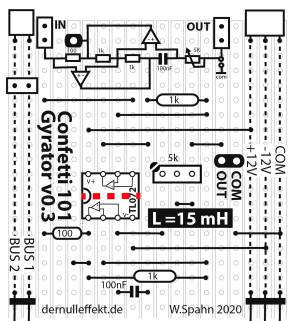
L = 15 mH inductor or a gyrator
NR = Chua's Diode
If the potentiometer is adjusted on the right position the circuit will oscillate in a chaotic manner.

Build
One can build a Chua's Circuit with the analog computer Confetti. Two modules are needed: the Chua's Diode and a Gyrator. A Gyrator is more handy than an inductor so one can use it instead.
Chua's Diode
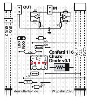
There are different ways to implenent a Chu's Diode, an alternative Chua's Diode one finds here:
Confetti 102 Chua's Diode (with real diodes)
Gyrator
Power Supply
One needs a power supply, too. To get the positive and the negative 9V to power the Confetti boards the easiest way is to use two 9V batteries.
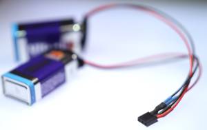 9V Battery Supply
... and some Caps and a Poti
To build a Chua's Circuit out of these board one needs additionally a breadboard or a Confetti302 Breadboard, some jumper wires, and these parts:
- Capacitors:
- 1x 100 nF
- 1x 10 nF
- Potentiometers:
- 1x 5 kOhm
Audio Out
For attaching the circuit to an audio mixer one should use an additional high Ohm resistor. Something like 500 KOhm should do.
A much better way would be to use a buffered audio output.
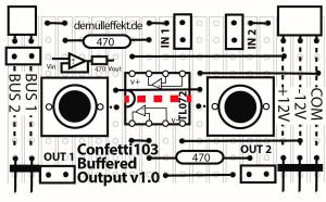 Confetti103 Buffered Output
Setup
A final setup could look like that:

Schematic

Buy the Parts
One finds all parts on mouser.de:
https://www.mouser.de/ProjectManager/ProjectDetail.aspx?AccessID=2db9b9b476
or as a PDF:
warenkorb_mouser.de_mai09_0601.pdf
Additionally one needs some double sided tape to stick the paper printout on the Veroboaord and some copper wire for the PCB bridges and some breadboard jumper wires.
It is also possible to replace the TL072 operational amplifier with an LM358, both work the same.
See and Listen to it
One can connect an audio mixer (with a 500 kOhm resister) and oscilloscope probes to three different points. X and Y are at the connection of the capasitor and the poti. The third one (Z) is on the gyrator board.

An oscilloscope in X-Y mode should look like that:

Links
https://www.chaotic-circuits.com/
http://www.chuacircuits.com/
http://nldlab.gatech.edu/w/index.php?title=Group_3_2012
http://www.instructables.com/id/A-Simple-Chaos-Generator
http://www.scholarpedia.org/article/Chua_circuit
http://crossgroup.caltech.edu/chaos_new/Chua.html
http://jamesnsears.com/archive/ecechua.htm
https://hypertextbook.com/chaos/strange/
https://www.vanderbilt.edu/AnS/psychology/cogsci/chaos/workshop/WorkshopF.html
Thanks
This tutorial has been made possible with AMRO20 - Art Meets Radical Openes, 2020.
License
Except where otherwise noted, the tutorial and all boards are made by Wolfgang Spahn 2016-20.
They are licensed under a Creative Commons Attribution-NonCommercial-ShareAlike 4.0 International License.
