Table of Contents
Paspberry Pi Pico
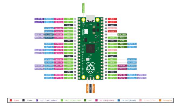
Pinout

schematic from raspberrypi.org
On ADC 04 is a temperature sensor.
The on board LED is on GP 25.
To reset short the RUN pin low.
Micro Python
Plug in the RP Pico with pressed BOOTESL button.
Download the Pico Firmware:
wget "https://micropython.org/resources/firmware/rp2-pico-20210510-unstable-v1.15-89-gd0de16266.uf2"
Copy it to the RP Pico
MicroPython on Command Line
start minicom
$ minicom -o -D /dev/ttyACM0
press Enter
 >>> from machine import Pin
 >>> led = Pin(25,Pin.OUT)
 >>> led.high()
 >>> led.low()
To leave minicom: Ctrl+A, Z, x
MicroPython in Thonny
Install Thonny:
yaourt -S thonny
Select Micro Python (Raspberry Pi Pico) on the bottom of the IDE or in Tools/Options/Interpreter.
Run blink:
import machine
import utime
led_onboard = machine.Pin(25, machine.Pin.OUT)
while True:
    led_onboard.value(1)
    utime.sleep(5)
    led_onboard.value(0)
    utime.sleep(5)
And the first audio code, if one connects a wire to ADC 0 one get the simple Theremin:
import machine
import utime

led_onboard = machine.Pin(25, machine.Pin.OUT)
led_onboard.value(1)

sensor_poti=machine.ADC(0)
sound_pin=machine.Pin(15, machine.Pin.OUT)
while True:
    reading=sensor_poti.read_u16()
    # values from 304 to 65535
    # print(reading)
    pitch=reading / 655350
    sound_pin.value(1)
    utime.sleep(pitch)
    sound_pin.value(0)
    utime.sleep(pitch)
Save it on the Pico
- for testing press F5 or the Run button
- Shift+Ctrl+F2 or the Stop button to stop again
- save the program as 'main.py' on the Raspberry Pi Pico
More sound with PicoBuzz by benevpi.
Power
 VBUS – USB power, 5V
 VSYS – power in (2-5V)
 3V3 – power out 3.3V, 300mA
 3V3_EN – disable internal voltage regulator
 RUN – enable, disable or reset
PWM
pwm=PWM(Pin(25))
pwm.freq(1000)
one can change the duty cycle, 0 to 65535
pwm.duty_u16(duty)
ADC
The Raspberry Pi Pico has four 12bit analog to digital converter:
ADC_VREF    (voltage reference)
GP28 - ADC2
AGND        (analog ground)
GP27 - ADC1
GP27 - ADC0
The fourth ADC is internally wired to a temperature sensor.
Characterizing the Raspberry Pi Pico ADC by Mark Omo.
Interrupt
from machine import Pin

mypin=Pin(2,Pin.IN,Pin.PULL_UP)
mypin.irq(lambdapin:print("IRQ with flags:",pin.irq().flags()),Pin.IRQ_FALLING)
or
mypin.irq(trigger=machine.Pin.IRQ_RISING, handler=myTask)
Multicore
 import _thread

 _thread.start_new_thread(Blink, ())
Synchronize two threads with allocate_lock()
baton = _thread.allocate_lock()
in the threads
 baton.acquire()
 ...
 baton.release()
taken from Andreas Spiess on youtube
Programmable I/O
Links & Projects
WS2812
https://makersportal.com/blog/ws2812-ring-light-with-raspberry-pi-pico
Usb Micro
https://www.hackster.io/sandeep-mistry/create-a-usb-microphone-with-the-raspberry-pi-pico-cc9bd5
License
This manuals is made by Wolfgang Spahn 2021.
Except where otherwise noted, content on this wiki is licensed under the following license: Creative Commons Attribution-NonCommercial-ShareAlike 4.0 International License.

